WHAT IS SCOUT?
The Scout scan head laser welding system is revolutionizing performance and utility in a remarkable array of scan head laser welding applications.
Our intuitive vision scan repositioning function can relocate parts that are
out of alignment and zero in for a perfect weld at micron accuracies.
The Scout system utilizes state of the art software combined with advanced vision technology and laser processing.
Our cutting edge software was developed to allow effortless
high precision laser welding applications.
Our simple and easy system allows you to cut setup times from hours to minutes for incredible results. The Scout is the industry benchmark for scan head laser welding.
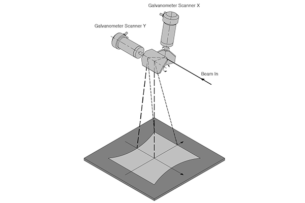
Galvo Scan System
Vision
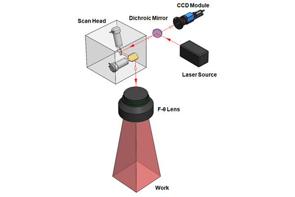
SCOUT System
Features
- Global leader in Scan Head Laser Welding
-
Ultra high precision vision combined with state of the art laser
processing software - Market leader in accuracy, precision, and ease of use
- Revolutionary part repositioning for out of alignment pieces
-
Pre-programmed geometric images for simple and easy setup,
no measurements -
Cutting edge software allows effortless high precision scan head
laser welding applications -
Robust, solid, design and construction for
long life production applications
Coaxial camera
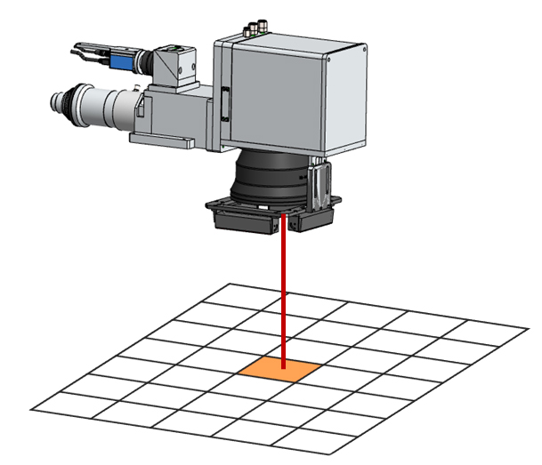
- The CCD camera can only see a very limited area.
- It can only process a very small live image
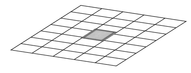
One Image
- Live image through coaxial CCD
- One pixel image of coaxial CCD
Scout
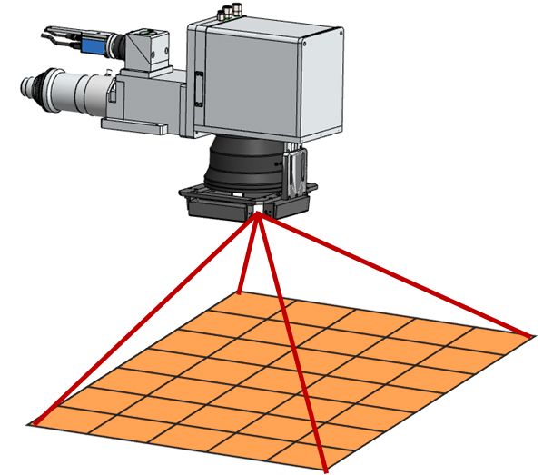
- The Scout takes an image of the whole working area, using our galvo-scanner.
- Using K-Lab image processing technology the Scout combines everything into one image
- Our technology then synchronizes the laser beam with the processed image.
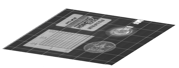
Hundreds of Images
Through vision image processing, the Scout can combine hundreds of images into one single clear image without any distortion.
Step 1. Image Capture
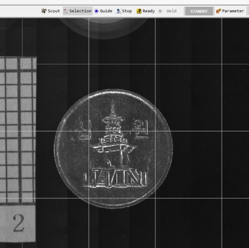
The entire working field is captured using the Scout image acquisition function. The user is actually looking at the working field on the computer screen. The welding targets are easy to view on the screen.
Step 2.Creating part welding patterns
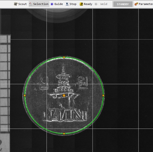
The user creates a welding pattern on the captured part image using simple, intuitive, drag and drop, pre-programmed geometric shapes and forms. The image on the screen can be enlarged for incredible accuracy. There are no complicated measurements necessary.
Step 3. Welding
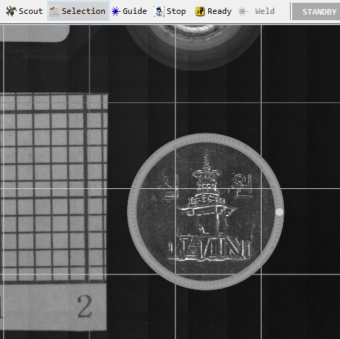
When the laser is emitted, the part is laser welded to the exact position as outlined. It is not necessary to do a number of time consuming teaching tasks in order to find the exact welding position. It is the most user friendly technology available. Setup times are cut down from hours to minutes.